With the continuous progress of science and technology, the overall level of industrial automation has been greatly improved.
Automatic feeder for power press is a kind of automatic equipment which supplies materials automatically and assists factory production. It is an indispensable part of human life and production. This paper mainly studies the transportation and loading positioning of the screw retaining ring by the automatic feeder for power press, and intellectualizes the control and improvement with the programmable logic programmer.
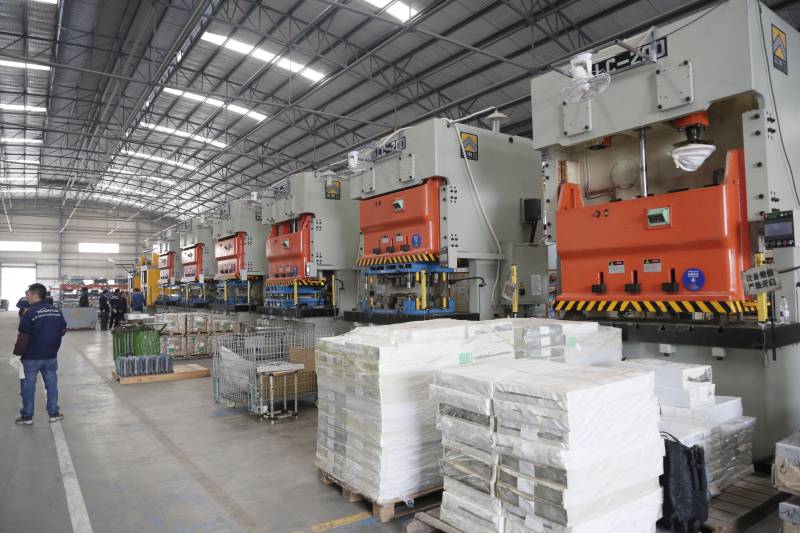
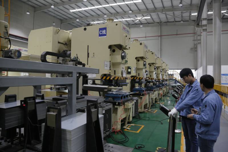
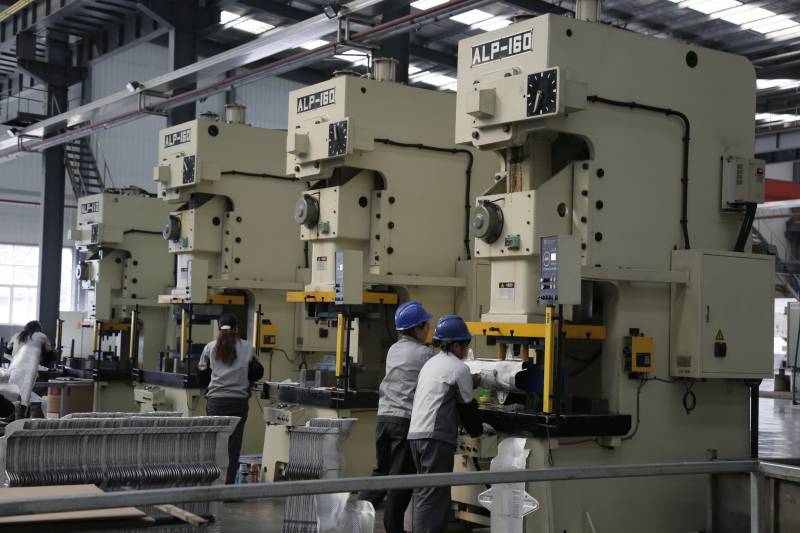
At present, the commonly used feeder, whether it is air feeder, roller feeder, NC feeder, gear feeder or high-speed clip feeder, is composed of material rack, leveling machine, feeding device (feeder), punch and continuous die, feeding device (feeder). These devices form complete automatic stamping Production line [1] along the direction of material feeding in turn. This paper studies the stamping and positioning accuracy of screw retaining ring press controlled by PLC and its development prospects and applications. Programmable processors are used to reduce errors. At the same time, reliability analysis and fault handling methods are studied to improve the processing accuracy and efficiency.
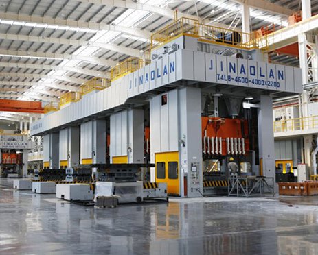
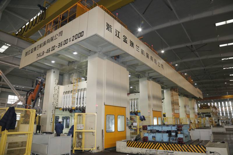
Structure and Principle of Automatic Feeder for Power Press
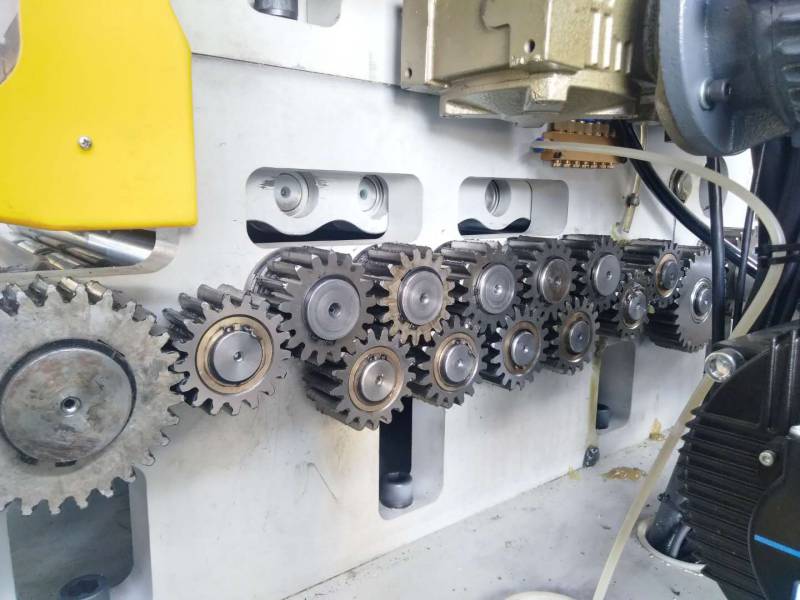
The base of stamping machine and the base of automatic feeder for power press are fixed on the workbench. The part of automatic feeder for power press locates in the rear. The upper part of the overlook is the vibration tray and screw feeding track of the automatic feeder. The screw retainer or workpiece enters the screw feeding track through the vibration tray, and then enters the pre-pressing position along the screw feeding track. The motor which is used to drive the vibration tray is Servo AC motor. Servo AC motor has high precision and sensitivity. The motor is located at the base. The closed-loop system controls the overall stability of the automatic feeder for power press pressed under the screw retainer.
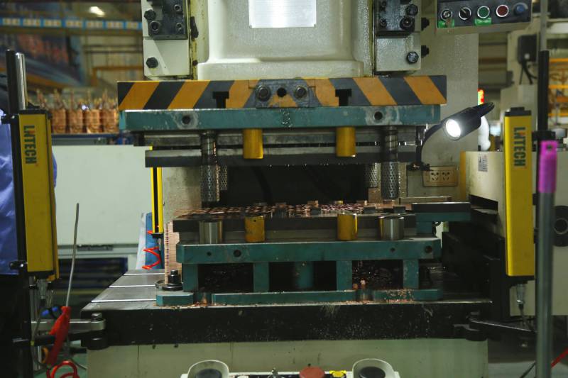
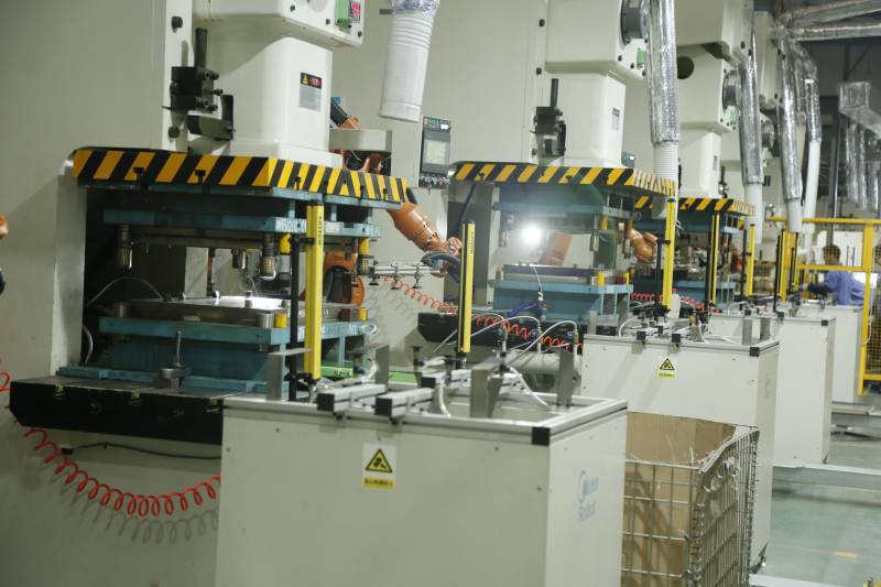
Firstly, the operator puts the worn lifting ring on the tooling, and the sensor detects the existence of the workpiece, and sends the detection signal to the PLC processor, which controls the action of the cylinder, and the device detects the total length of the bolt in real time. Start the equipment, and the workpiece has been pre-positioned, and the detection signal is transmitted to the PLC processor, which controls the action of the transmission device, and moves the screw retaining ring through the feeding device and the vibration disk [3]. When the positioning sensor detects that the workpiece is in a predetermined position, it transmits the signal to the control system. After receiving the signal, the control system transmits the instructions to the PLC processor to control the cylinder action. If it does not meet the requirements, the device does not start. On the contrary, the device starts and automatically sends the screw retaining ring to the top of the bolt, and the device starts to press down.
When the downward pressure of the equipment reaches the limit position of the workpiece, the total height of the fixtures (sleeve and gasket, etc.) on the bolt is detected by the displacement sensor. If the total height does not match the preset parameters of the equipment, the equipment will stop working by alarm; otherwise, the downward pressure will be completed. When the workpiece is processed, the PLC processor controls the clamping cylinder to loosen, and moves the workpiece to the appropriate position. It removes the processed workpiece, and puts it into the unprocessed workpiece, and circulate the processing like this. The pneumatic flexible clamping system mainly includes: control device, detection device, positioning device, clamping device and workpiece removal device.